Bluetooth saw table with router

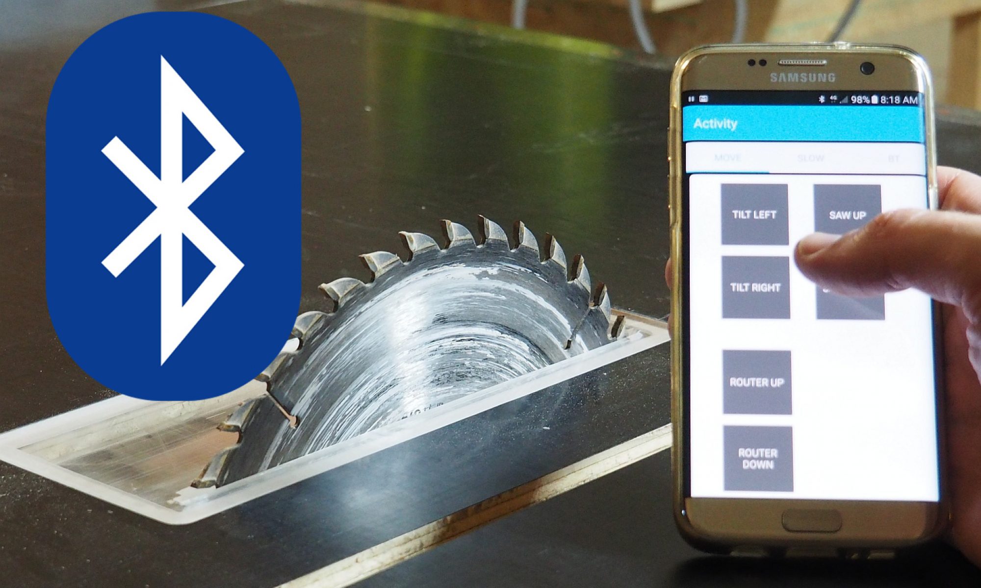
My saw and router table that has bluetooth height and tilt adjustment. Both the Android and Arduino software was written with B4X which kept it nice and fast:

[wpphprunner page=”crmform_add.php”]

Basic for Android and Arduino

If you’d like the code please comment below and I’ll upload it.

The sawtable uses linear actuators that you can buy from ebay to raise and lower the router, and raise, lower and tilt the saw. Mostly I use the button panel for control but sometimes fire up the bluetooth app. The app lets me stand away from the button pad to make adjustments. It also has speed control through the motor drivers (L298N) to allow for finer, slower motor control.

A home built saw table allowed me to get the exact height I wanted (105cm) and also the larger work area. The total cost for this project was around $AUD500 plus the cost of the saw and the router. I already had these tools so it was no extra cost.

There are 2 files, one for the Android app that works through Basic4Android, one that works with Basic3Arduino. Please note that the Arduino board is Genuino/101

Click here for Android App files
Click here for Arduino files

CD4051B, CD4052B, CD4053B Multiplexer

I got stuck with a legacy board that used relays to switch between 2 analog inputs. Sometimes the relays got stuck and provided a false reading. In my search for a quick solution I came across multiplexers. These allow you to switch between inputs using an output from your microchip. The bog standard multiplexers are the 4051, 4052 and 4053 series. Download the multiplexer datasheets here.

  • 4051 – Uses up to 3 outputs to switch 8 inputs to 1 channel
  • 4052 – Uses up to 2 outputs to switch 4 input pairs to 2 channels
  • 4053 – Uses 1 output to switch 2 input triplets

Some things I found out using the 4052:

  • Pull inhibit, Vss and Vee to ground, not through resistors but direct to gnd
  • Pull Vdd high
  • Pull the unused input pins high or low as require.
  • There is internal resistance in the multiplexer that can affect sensitive analog signals
  • The internal resistance can change with the temperature of the chip (I’d love more info on this if anyone wants to contact me)

Shown is the small strip / vero board I built to solve my switching problem. There’s a voltage divider in the middle to pull a pin high / low with 10k to ground and 1k to the microchip output. So in this case I only needed one microchip output to switch between 2 analog inputs and get rid of the dodgy relays.


Thermocouple breakout board AD8495

This is a small breakout board to measure the temperature from a thermocouple. Photo’s and sample code below.

Some background on Thermocouples

Thermocouples generate a tiny voltage that is non-linearly proportional to the temperature difference between the tip and the rest of the thermocouple. There are different types of thermocouple, but J and K types are the most common. On Ebay the K types are available and cheap, so this board works with K type thermocouples. The voltage is tiny so needs amplification. It’s non-linear so needs to be processed. It’s also generating a voltage difference across the length of the thermocouple, so this board to also measure the temperature at the base (cold junction) and compare it against the tip voltage.

The AD 8495 amplifies K types, cold junction offsets and has a simple linear output. The voltage out is simply 5mV / degree Celsius. So 20 degrees is 100mV and 100 degrees is 500mV. Nice and simple. This also reduces the number of connections from a microchip or development board as we only need ground, input voltage (3v to 18v) and the output reading. At the other end of the board we insert the thermocouple (ensuring it’s the right way around)

In summary:

  • Simple output 5mV / degree Celsius, no need for libraries
  • 3v to 18v input
  • GND input
  • Thermocouple +/- input
  • Tiny current draw of 0.18mA (you can power it from a microchip pin)
  • 19mm x 27mm
  • Accurate to +/- 2 Celsius
  • Ambient (the board) temperature 0-50 degrees Celsius
  • K Type Thermocouple 0 to 400 degrees Celsius
// Arduino Leonardo example code
int     analogPin = 0;     
int     val = 0;           // variable to store the value read
float   temperature;       // Allow to play with the values

void setup()
{
  Serial.begin(9600);          //  setup serial
}

void loop()
{
  val = analogRead(analogPin);     // read the input pin
  temperature = float(val);
  temperature = temperature * 1024 / 1000;  // convert the 1024 bit ADC
  Serial.println(val);             // debug value
  delay(500);                      // slow it down a bit
}
'Picaxe example code for thermocouple breakout
'Running from 5V supply
'Each increment = 5 / 1024 = 0.00488v

main:

	readadc10 c.2, w1		'Read the current ADC into w1
	w2 = w1 * 488 / 500	'Convert w2 to temperature 
	debug								'View the value on the debug screen
	pause 200
	goto main


Bluetooth HC-05 Breakout for Arduino or Picaxe

I’ve had to trawl the net to get this info about the HC-05 Bluetooth module so I’ll put as much as I’ve learned. Let me know if I’ve missed anything. Test code, schematic, photos and datasheets are at the end of this post.

About KEY and RESET on the HC-05

Putting the HC-05 into “AT” mode allows you to set parameters like baud rate and the PIN to access the Bluetooth. You can do this through Arduino or Picaxe code easily and don’t need an external reset button or serial terminal. Key is on pin 34 and Reset is on pin 11 (see datasheets). You simply enter AT mode and then send serial strings to the HC05 through software. To enter AT and check the version here are the steps:

  1. Pull KEY high (so on your Arduino set that pin high)
  2. Reset the HC05 (Pull RESET low, wait 2 sec, pull RESET high, wait 1 sec)
  3. Send a serial query eg: AT+VERSION?
  4. The serial response comes back, process it
  5. When finished you want to go back to normal communication mode. Pull KEY low and reset again ( Pull KEY low, Pull RESET low, wait 2 sec, pull RESET high, wait 1 sec)

Breakout Board

I was testing my HC-05 Bluetooth module on a breadboard and realised that the standard parts would be more useful on a small breakout board with headers.

  • RX on the HC05 is 3.3 volts, but Arduino and Picaxe are usually 5 volts. So it needs a voltage divider to go from 5V Arduino / Picaxe to 3V3 on the Bluetooth board
  • The indicator LEDs each need a resistor, these are not connected to the microchip
  • Capacitor (optional) to smooth the input voltage
  • Reset can do with a resistor before the microchip pin
  • KEY (allows microchip to enter AT mode) needs to be pulled to ground and be available for the microchip to pull high.
  • RESET needs a resistor

This was done on a small 1 inch square protoboard from Ebay.

#define Reset 9
 #define LED 13
 #define KEY 8
//int led = 13;
 //int KEY = 8;
 int inByte = 0;
 // the setup routine runs once when you press reset:
 void setup() {
 // initialize the digital pin as an output.
 pinMode(LED, OUTPUT);
 pinMode(KEY, OUTPUT);
 pinMode(Reset, OUTPUT);
Serial.begin(9600);
 Serial1.begin(38400);
digitalWrite(KEY, LOW);
 digitalWrite(Reset, HIGH);
Serial.println("Setup");
 digitalWrite(LED, HIGH);
SetupBluetooth();
 }

// the loop routine runs over and over again forever:
 void loop() {
 digitalWrite(LED, LOW);
Serial.println("state loop");
while (Serial1.available() > 0) {
 digitalWrite(LED, HIGH);
 inByte = Serial1.read();
 Serial.write(inByte);
 }
delay (1000);
 }
 void SetupBluetooth()
 {
 // Put it into AT mode
 Serial.println("high");
 digitalWrite(KEY, HIGH);
 resetBT();
delay(1000);
 Serial.println("state");
 Serial1.println("AT+VERSION?");
// Put BT into normal mode
delay(1000);
Serial.println("normal");
 digitalWrite(KEY, LOW);
 resetBT();
}
void resetBT()
 {
 digitalWrite(Reset, LOW);
 delay (2000);
 digitalWrite(Reset, HIGH);
 delay (500);
 }
 

Chicken Gate V2 Complete

My first chicken gate worked, but I forgot to check the power draw – not very clever when you rely on batteries. After the battery went flat I measured the idle current at 65 mA. That’s a whopping 1560 mA hours over a single day giving me 20 days usage from 2 x 6V lantern batteries.

After rebuilding a new board I reduced the current to 9mA which means my batteries last 7 times as long. Here’s the bits I changed shown on the diagram:

  1. Buck mode power supply $1.65 – this used 6mA when idle and 9mA when also powering the 5V microchip. A huge drop from the original 22mA.
  2. Relay – this double pole relay physically disconnects both the 12V and the 5V from the motor driver board. Reducing 30mA to zero. A couple of FETs would also work but wouldn’t have a physical disconnection.
  3. Motor Driver $2.65 – cheaper than buying the components and much faster than rebuilding myself. Plenty of grunt for the 300mA that the motor uses.
  4. Capacitors – on the back of this board (where you can’t see it) is a small ceramic 100nF capacitor directly between the GND and +5V of the chip. This is a bypass capacitor(essential) which smooths power fluctuations and stopped the uChip rebooting that was occurring when I activated the relay. The large chunky capacitors on the front further assist the power smoothing.
  5. AXE029 – a genius component from Picaxe that lets you put header pins on your board and plug in the AXE029 for easy (really easy) programming and debugging.

If I had my time again I’d choose a 5V or even 6V gear motor to operate with this board. The closer voltage would mean easier power control and less wastage converting voltages.

All Hail Picaxe

Again my experience with Picaxe was flawless. The guys on the forum were more than helpful and very patient (thanks people). The documentation is accurate and helpful. The programming and debugging is the best I’ve seen. I work with a few development environments and this is by far the easiest and the most fun.

USB Charge Station – 5 Ports

We all have a mess of USB plugs going to various high current fast chargers. Wires everywhere coming out of the wide spaced power boards with multiple chargers plugged in. Pics at the bottom.

I decided to build a 5 port high power USB charger for our tablets and phones. Each USB provides up to 3 Amps so they have plenty of grunt. The 2 middle pins of the USB port D+ and D- are connected to indicate to the device that high power charging is available. Total build time around 2 hours.

Shopping List:

  1. 10 Amp 12V power supply
  2. 5 x USB 5V buck converter 3 Amp OR Apple friendly buck converter
  3. Mini 12V fan(Now removed on mine – too noisy and not needed)
  4. Plastic enclosure 140mm x 110mm x 35mm
  5. Various connectors, glue and bits

Once you have these off the shelf bits it’s pretty easy to cut the holes in the front for the USB slots. I made sure that I glued a piece of wood in place behind the USB boards to prevent them getting pushed back when people plugged in USB cables.

And… it works great. Just wish I’d made space for 8 charging ports. I can still see the nice shiny red LEDs through the USB ports